I've bought old, broken and hence cheap, Tesla counter BM520. It's classical piece of equipment build with TTL 74xx family chips and with nixie tubes for display.
The good thing about this kind of vintage equipment is that it was made to be repaired and that there are schematics available, you can get even scans of the original manuals easily from the internet.
This particular unit, apart from being very dusty, had a few broken transistors and trimming pots in the power unit, which was fairly easy to spot and fix.
If you are wondering about the specs the maximum frequency is 12.5Mhz although it seems to be working fine up to 15Mhz for me.
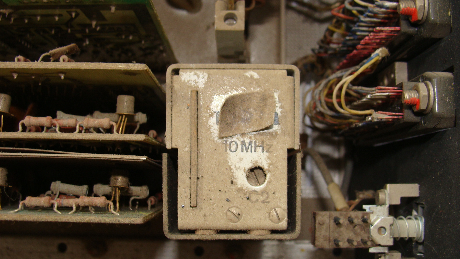
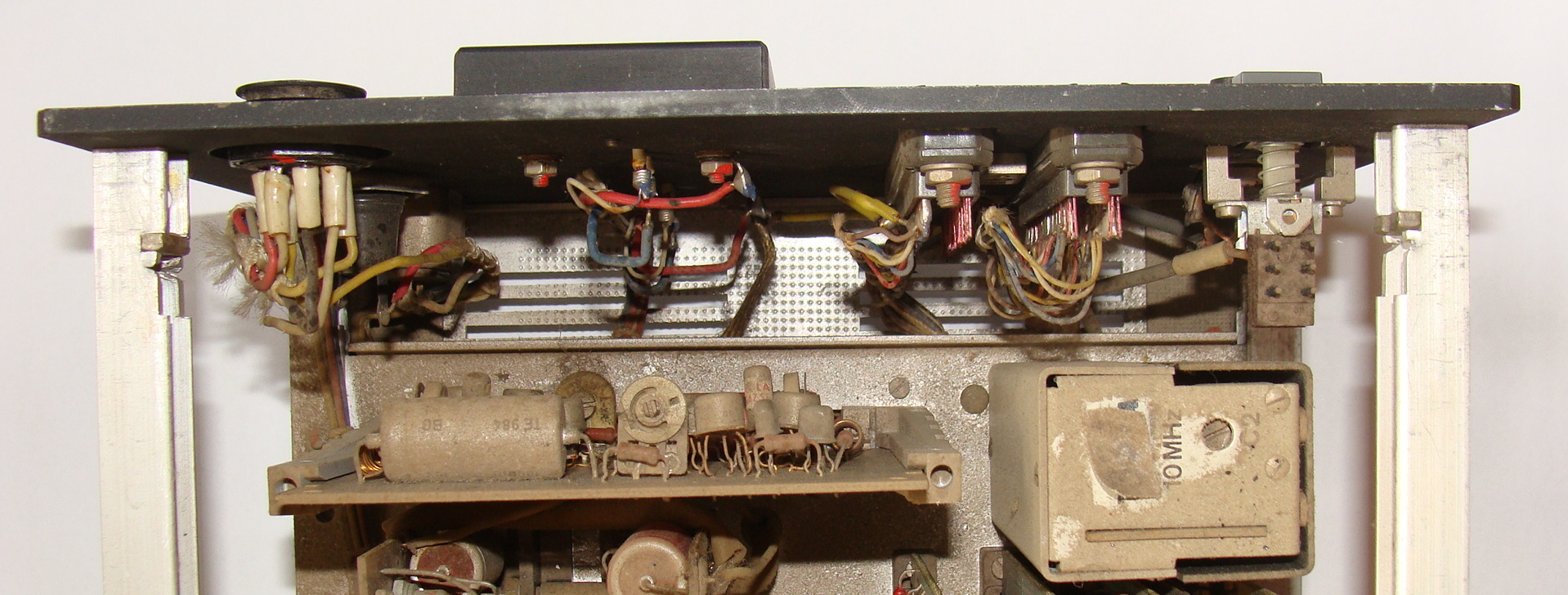
The timebase is driven by a 10Mhz crystal oscillator that is termostated to a constant temperature and should be correct for six decimal places that are shown on the display. I haven't verified the precision yet and I would expect that the frequency is slightly off after all these years.
As I examined the boards I've been surprised that some of the digitron driver chips 74141 were made by Texas Instruments. Originaly I've thought that this particular unit has been repaired once already. But later on I've been told that sometimes Tesla was too slow to produce chips and had to buy them from capitalistic countries instead.

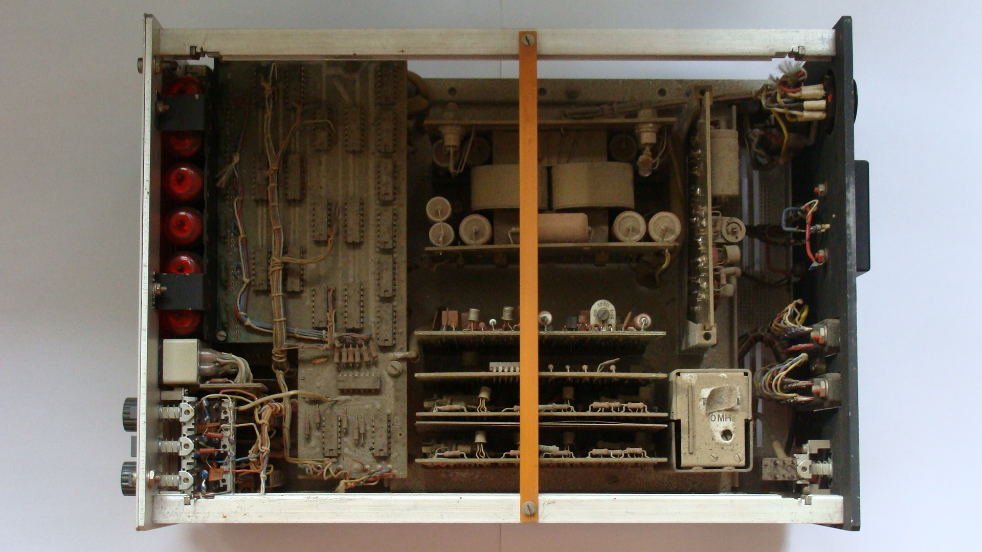
Here we are looking at the power source unit next to the 10Mhz oscillator, the power transistors are actually mounted on the back of the unit in the classical TO-3 packages. The board produces two voltage levels, that is +5V for TTL chips and +12V for amplifiers.
And by the way the connectors on the right are printer interface, the data shown on the display are available on these two connectors in TTL levels, it would be quite easy to add USB interface with atmega to capture the measured data.
There were three faulty transistors in small metal can packages, which is common mode of failure for these. The two transistors driving the power transistors were simply dead. While the last transistor disconnected from the board because one of the leads was completely rusted off. Such transistor can be easily lifted off the board without much force. There are two reasons why this happens to old tesla transistors, first of all when there was shortage of copper transistor leads were made from iron with gold plating on the top. The iron tends to rust off and eventually you may end up with hollow leads that are composed mainly of rust and thin gold layer on the top. Secondly the small metal cans are sealed on the bottom with a glass that contains additives to lower the melting point, unfortunately some of the additives are also corrosive which only speeds up process.
As I said earlier three trimming pots needed to be replaced, the wipers were not making good contact anymore. This usually happens when they are close to heat source which causes thermal cycling, which may have been the case here, since the board is stacked between the main transformer and the power transistors.
Here is my hand-drawn schematic of the PSU with some annotations. The schematic in the original manual follows how the components are placed on the board, while this one is divided into a functional blocks.

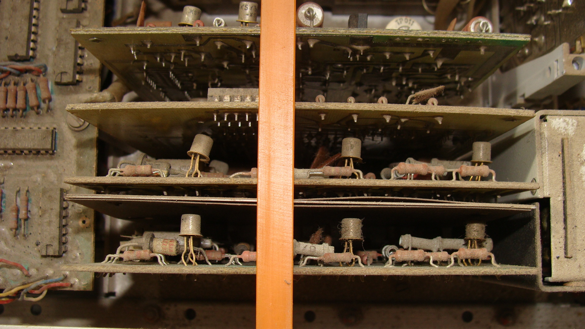
Photo of the swapable boards before cleaning, the two boards on the bottom separated by a metal shield are wideband amplifiers, the boards on the right contain the logic circuits implementing the different counter modes in 74xx silicon.